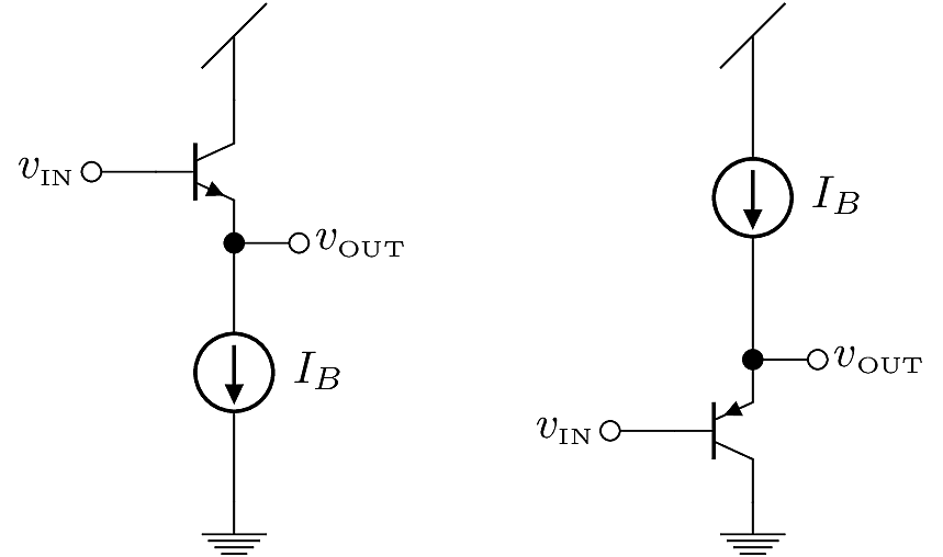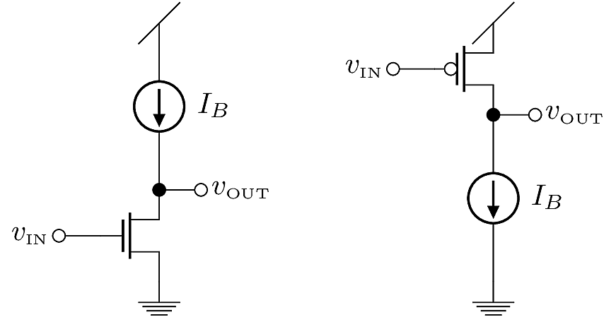
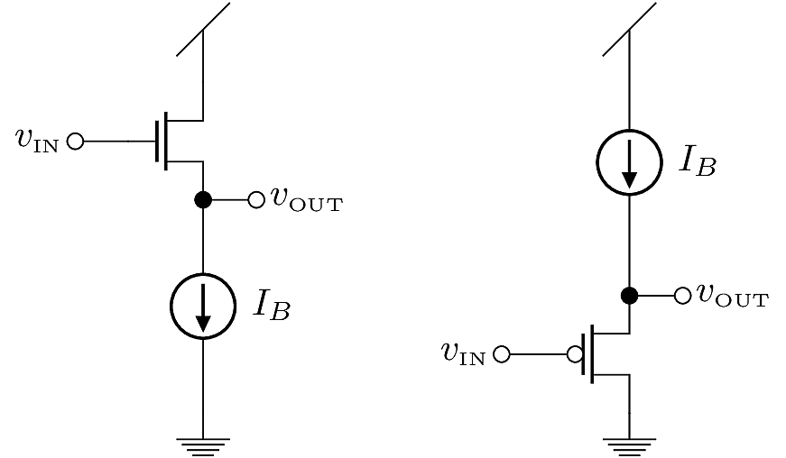
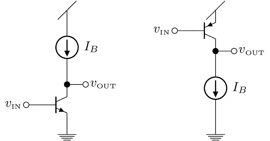
For MOSFETs and BJTs, there are three basic configurations used for linear signal-flow analysis. These configurations most commonly appear in analog amplifier designs, but are also relevant for some types of digital circuits. This section gives a brief summary and schematic for each configuration. In each case, the configuration is defined by its input terminal and output terminal, and is named for the idle terminal. In small-signal models, the idle terminal is called “common”, so we have names like “Common Source”, “Common Emitter”, and so on.
Input: Gate
Output: Drain
Common: Source
Input: Source
Output: Drain
Common: Gate

Input: Gate
Output: Source
Common: Drain
Input: Base
Output: Collector
Common: Emitter
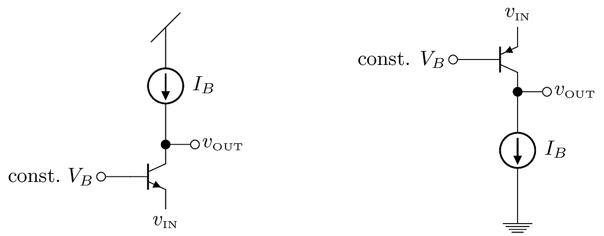
Input: Emitter
Output: Collector
Common: Base
Input: Base
Output: Emitter
Common: Collector