
In the time it takes for a user to push a button or type a key, millions of clocks cycles may pass. Usually the user’s intention is to trigger a single event, not millions of them. To make things more complicated, buttons and keys tend to “bounce” when switching between 0 and 1. Instead of a clean transition, the signal may flutter back and forth before settling into a clear logic level. So a good Human Interface Device (HID) should reject the bouncing and reduce a long keypress to a single clean pulse lasting one clock cycle.
The debouncing problem also introduces the concept of asynchronous interfaces. A human user is not synchronized to the digital system’s clock, so the system needs to do some work to detect the information. The same problem occurs whenever signals needs to be exchanged between different digital systems that are on separate clocks. Such systems are not synchronized, hence they are called asynchronous.
The simplest debouncing strategy is to make a register assignment, like this:
module debouncer
 (
   input       clk,
   input       btn,
   output reg  btn_db // debounced output
 );

  always @(posedge clk) begin
     btn_db <= btn;
  end

endmodule
This always code is
sensitive to posedge clk,
so the value of btn is evaluated
only at the rising edge of the clock. That should take care of any
“fast” bouncing. Slower bouncing can be resolved using a clock divider
to make the assignments less frequent.
This method doesn’t resolve the long button press problem. What we really want is to trigger a single clock cycle pulse regardless of how long the button is held down. One way to do this is by adding delay registers as in the code below.
module debouncer
 (
   input       clk,
   input       btn,
   output reg  btn_db // debounced output
 );

  reg btn_d; // button delay by one clock cycle

  always @(posedge clk) begin
     btn_d  <= btn;
     btn_db <= btn & ~btn_d;  // true only when btn rises from 0 to 1
  end

endmodule
Here there are two concurrent non-blocking
assignments. These assignments take effect in the next (future)
clock cycle. That means the btn_db assignment compares the value
of btn now to its value in the
previous cycle. The btn_db
output is only 1 for a single
clock cycle, when btn changes
from 0
to 1.
This style of debouncer is a good start, but still misses a bounce from time to time, resulting in unintended double-press errors.
A more robust debouncing approach is to ensure that the btn signal is 1 continuously
for some number of clock cycles, and then settles to zero for a number
of cycles. A standard way to count clock cycles is to use an alarm
timer. An example is given in src/tcounter.v,
listed here:
module tcounter
  #(
     parameter N=100
    )
   (
     input      clk,
     input      rst_l,
     input      clear,
     output reg done
   );

   integer     clk_count;

   always @(posedge clk, negedge rst_l) begin
      if (!rst_l) begin
        done      <= 0;
        clk_count <= 0;
      end
      else begin
        if (clear) begin
           clk_count <= 0;
           done      <= 0;
        end
        else if (clk_count == N)
           done <= 1;
        else
           clk_count <= clk_count + 1;
      end
   end
endmodule // tcounter
In this module, the alarm is reset when clear is 1. When clear drops from 1 to 0, the timer
starts counting. Once N clock
cycles have elapsed, done rises
from 0
to 1 and
stays high until another clear
signal is given.
Using this alarm timer, we can design a debouncer state machine with three states:
Let’s analyze the behavior in each of these states:
btn event. There are two outgoing
transitions:
clear is held at 1 so the tcounter is prepped.btn goes to
1, the
machine goes to state 1 and lowers
clear to start the alarm
counter.btn has gone to 1, and clear is 0 so the tcounter is running. There are three
outgoing transitions:
btn is 1, it waits
for the alarm t to
complete.btn “bounces” (i.e. goes back to 0) before the
alarm signal t, then the machine
resets to state 0.btn was stable at 1 until the
alarm t, then the machine is
allowed to proceed to state 2 when btn falls to 0. During this
transition, the output btn_db is
set to 1, and clear is set to 1 to reset the
tcounter.btn_db is set to 0 so that the
output pulse lasts a single clock cycle. There are two outgoing
transitions:
clear to 0 to start the
alarm timer. This creates a delay to allow any release bouncing to
settle.t is 1, the machine
returns to its initial state. The condition is t & !clear
since both t and clear are 1 upon exiting
state 1 (it takes an extra clock cycle for the tcounter to reset itself).localparam for
Descriptive State NamesNumerical state values can be confusing when analyzing a complex or
high-level FSM. Many designers prefer to use Verilog constants with
local scope (i.e. defined only within the module). This is done using
the localparam
syntax.
Instead of using states 0, 1 and 2, we give
them names:
localparam WAIT    = 0;
localparam PRESS   = 1;
localparam RELEASE = 2;
Later in the code, these names can be used as if they were numerical constants.
Create a file named src/debouncer.v
and declare a module named debouncer. Use the code fragment shown
below as a template. The first state is already done.
module debouncer
  (
   input clk,
   input rst_l,
   input btn,
   output reg btn_db
   );

   reg [1:0]  state;
   reg              clear;

   wire       t; // tcounter timer alarm

   localparam WAIT    = 0;
   localparam PRESS   = 1;
   localparam RELEASE = 2;

   // tcounter instance
   tcounter T1
     (
      .clk(clk),
      .rst_l(rst_l),
      .clear(clear),
      .done(t)
      );

   initial begin
      state  = WAIT;
      clear  = 1;
      btn_db = 0;
   end

   always @(posedge clk, negedge rst_l) begin
      if (!rst_l) begin
        state  <= WAIT;
        clear  <= 1;
        btn_db <= 0;
      end
      else begin
        case (state)
          WAIT:
            begin
              // btn_db is set to zero for all transitions
              // from this state
              btn_db <= 0;
              if (btn) begin
                 state <= PRESS;  // change state
                 clear <= 0;      // start the timer
              end
              else
                clear <= 1;
            end
          PRESS:
            begin
               // YOU DO THIS
            end
          RELEASE:
            begin
              // YOU DO THIS
            end
          default:
            // DEFAULT behavior is necessary since we aren't
            // using state 2'b11 ('d3). If the module somehow
            // arrives in state 3, we need to give it a way
            // back to normal functioning so it can recover
            // gracefully from faults.
            begin
               btn_db <= 0;
              clear  <= 1;
              state  <= WAIT;
            end
        endcase
      end
   end

endmodule // debouncertop ModuleWe will use a top-level wrapper module to do the following:
debouncerrst
button to active-low rst_l
signalbtn_db and use it to
toggle an LED outputmodule top
(
input clk,
input btn,
input rst,
output reg led
);
wire btn_db;
wire rst_l;
assign rst_l = ~rst;
initial begin
led = 0;
end
debouncer db1
(
.clk(clk),
.rst_l(rst_l),
.btn(btn),
.btn_db(btn_db)
);
always @(posedge clk, negedge rst_l) begin
if (!rst_l) begin
led <= 0;
end
// Toggle the LED if the button is pressed:
else begin
if (btn_db)
led <= ~led;
end
end
endmodule // topOpen src/testbench.v
and find the lines below. These create a stimulus pattern to simulate a
bouncing button press. The btn
signal bounces from 0 to 1 starting at
cycle 10, then remains stable at 1 until cycle
200, then bounces back to 0 until it
becomes stable again at cycle 235:
        case (clk_count)
          10: // start button press
            btn <= 1;
          20: // bounce
            btn <= 0;
          24: //bounce
            btn <= 1;
          30: //bounce
            btn <= 0;
          31: // now sustain
            btn <= 1;
          200: // release
            btn <= 0;
          210: // bounce
            btn <= 1;
          215: // bounce
            btn <= 0;
          230: //bounce
            btn <= 1;
          235: //sustain
            btn <= 0;

        endcase // case (clk_count)
The simulation is run until 500 clock cycles in order to verify that the state returns to zero after the button stabilizes:
   // DEFINE WHEN TO TERMINATE SIMULATION:
   always @(posedge clk) begin
      clk_count <= clk_count + 1;
      if (clk_count == 500) begin
        $fclose(fid);
        $finish;
      end
   end
Run the simulation using make
and you should see output like this:
clk:    11 clk diff:    11 state: 0 clear: 1 t: 0 btn: 1 led:  0
clk:    12 clk diff:     1 state: 1 clear: 0 t: 0 btn: 1 led:  0
clk:    21 clk diff:     9 state: 1 clear: 0 t: 0 btn: 0 led:  0
clk:    22 clk diff:     1 state: 0 clear: 1 t: 0 btn: 0 led:  0
clk:    25 clk diff:     3 state: 0 clear: 1 t: 0 btn: 1 led:  0
clk:    26 clk diff:     1 state: 1 clear: 0 t: 0 btn: 1 led:  0
clk:    31 clk diff:     5 state: 1 clear: 0 t: 0 btn: 0 led:  0
clk:    32 clk diff:     1 state: 0 clear: 1 t: 0 btn: 1 led:  0
clk:    33 clk diff:     1 state: 1 clear: 0 t: 0 btn: 1 led:  0
clk:   134 clk diff:   101 state: 1 clear: 0 t: 1 btn: 1 led:  0
clk:   201 clk diff:    67 state: 1 clear: 0 t: 1 btn: 0 led:  0
clk:   202 clk diff:     1 state: 2 clear: 1 t: 1 btn: 0 led:  0
clk:   203 clk diff:     1 state: 2 clear: 0 t: 0 btn: 0 led:  1
clk:   211 clk diff:     8 state: 2 clear: 0 t: 0 btn: 1 led:  1
clk:   216 clk diff:     5 state: 2 clear: 0 t: 0 btn: 0 led:  1
clk:   231 clk diff:    15 state: 2 clear: 0 t: 0 btn: 1 led:  1
clk:   236 clk diff:     5 state: 2 clear: 0 t: 0 btn: 0 led:  1
clk:   304 clk diff:    68 state: 2 clear: 0 t: 1 btn: 0 led:  1
clk:   305 clk diff:     1 state: 0 clear: 1 t: 1 btn: 0 led:  1
clk:   306 clk diff:     1 state: 0 clear: 1 t: 0 btn: 0 led:  1
The output lines are only printed when there is an
interesting signal change (see explanation in the next
section). In the first line of output at clock 11, we see btn go high, then the FSM state goes
to state 1 at clock 12. The btn
bounces a few times causing state to cycle between 0 and 1.
The btn signal stabilizes at
clock 33, and the alarm t is
finished at clock 134. At this point the FSM sits in state 1 until btn goes low at clock 201. At this
point the FSM transitions to state 2, and btn_db is pulsed causing led to toggle.
The FSM then loiters in state 2 until clock 304 when t fires again. At clock 305 the btn has stabilized, and the FSM is
back in state 0, ready to detect a new button press.
In this project we explore several new options for data visualization. Instead of straining over a raw cycle-by-cycle text dump, we can use several methods to make the data more interpretable.
To make the text output readable, we only print an output line when an interesting change occurs. To detect these changes, we use a set of delay registers and use XOR operations to detect when something has gone from 0-to-1 or 1-to-0:
   reg btn_d;   // delayed button (to detect changes)
   reg led_d;   // delayed led
   reg state_d; // delayed debouncer state
   reg clear_d; // delayed clear signal
   reg t_d;     // delayed timer alarm

   reg value_change; // 1 if something changes, 0 otherwise

   always @(*) begin
      value_change = btn ^ btn_d;
      value_change = value_change | (led ^ led_d);
      value_change = value_change | (DUT.db1.clear ^ clear_d);
      value_change = value_change | (DUT.db1.state ^ state_d);
      value_change = value_change | (DUT.db1.t ^ t_d);
   end

   always @(posedge clk) begin
     // print data summary only if there is a change:
     if (value_change) begin
        clk_count_d <= clk_count;

        $write("clk:  %4d", clk_count);
        $write(" clk diff:  %4d", clk_count-clk_count_d);
        $write(" state: %1d", DUT.db1.state);
        $write(" clear: %b", DUT.db1.clear);

        // ... and so on ... //
     end
endThese lines produce a tab delimited data file in
test_result.txt:
        $fwrite(fid,"%4d", clk_count);
        $fwrite(fid,"\t%4d", clk_count-clk_count_d);
        $fwrite(fid,"\t%1d", DUT.db1.state);
        $fwrite(fid,"\t%b", DUT.db1.clear);
        $fwrite(fid,"\t%b", DUT.db1.t);
        $fwrite(fid,"\t%b", btn);
        $fwrite(fid,"\t%d", led);
        $fwrite(fid,"\n");
A tab-delimited file can be imported by many software applications.
In Matlab, you can use the importdata command:
d = importdata('test_result.txt');The data is loaded into a matrix named d. You can plot columns from the data
using the plot, stem, or stairs commands, for example:
stairs(d(:,1),d(:,6))
xlabel('Clock Cycle')
ylabel('btn')xsim in GUI modeThe Vivado graphical interface can be used by running the simulation in GUI mode:
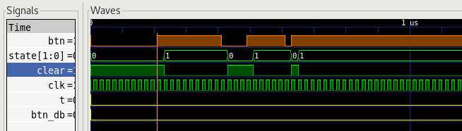
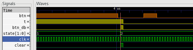
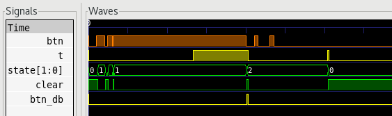
make guiThis allows using the graphical interface to zoom and view signals side-by-side:
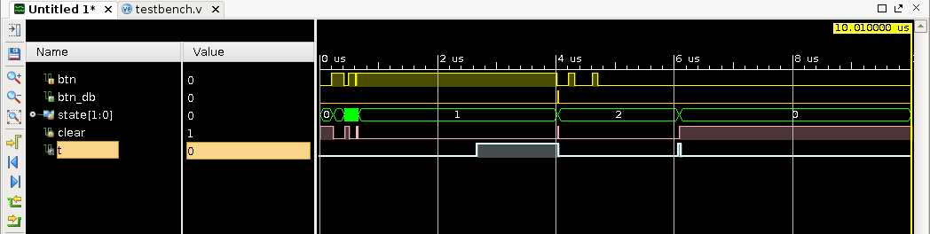
gtkwave to view vcd fileThese lines in src/testbench.v
direct the simulator to create a Value Change Dump
(VCD) file for the indicated module. VCD files are used to
exchange simulation data between a variety of analysis tools.
   // INITIAL SIGNAL CONFIGURATION:
   initial begin

      $dumpfile("debounce.vcd");
      $dumpvars(1,DUT.db1);

   end
The simulator will save all the signal changes in the db1 module and dump them into debounce.vcd. There are a number of
lightweight programs for viewing VCD files. One of the more popular
tools is gtkwave, which is a
multi-platform free option.
Copy the master XDC file, Basys3_Master.xdc to a new one named
debouncer.xdc. In debouncer.xdc, locate all the lines
corresponding to these ports, and move them to the top of the file:
clkbtnC – rename to rstbtnU – rename to btnLED[0]
– rename to ledThen delete all the other lines since we aren’t using any other resources.
Run make implement to build
your design, and program it onto the Basys3 board. Record a short video
showing yourself pressing the button a few times. The LED should toggle
ON/OFF each time you press and release the button.
Turn in your work using git:
git add src/*.v *.v *.rpt *.txt *.tcl *.bit *.xdc
git commit . -m "Complete"
git push origin main
Upload your video on Canvas to indicate that your assignment is done.